blogs
Qtech Technology Co., Ltd
SMT / DIP / PCB assembly /
Testing / BGA reworking
QUOTE
close
SMT / DIP / PCB assembly /
Testing / BGA reworking

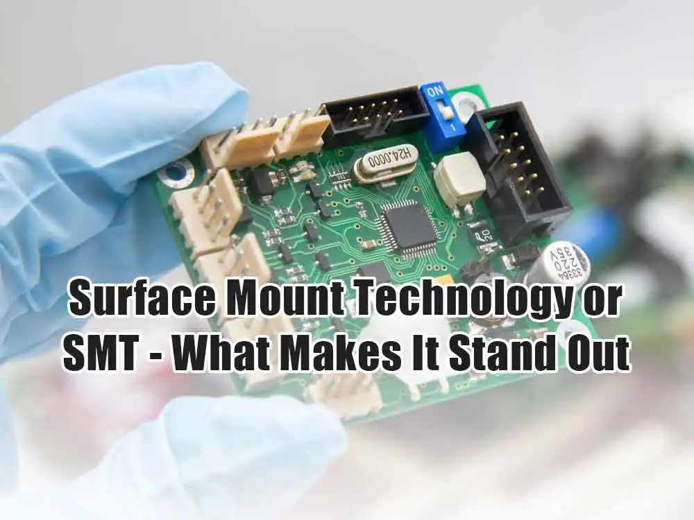
Printed circuit boards are used in almost all modern electrical devices. Electronic components installed on a printed circuit board make up their crucial element. Surface mounting and via installation are two methods for attaching components to a printed circuit board. In this piece, we define Surface mount technology as a process that is, in most situations, fully automated.
Since the 1970s, advancements in surface mount technology have accelerated. As a result, it has become a crucial component of the global electronics market. Surface mounting will eventually replace coated mounting as we shrink electronics and their constituent parts. In addition, Surface mount technology ensures that printed circuit boards may accommodate many components without compromising performance.
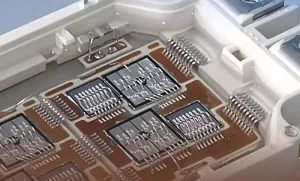
STM refers to a method of PCB component placement. Surface mount devices (SMDs) are used to attach electronic components to a printed circuit board and may be implanted from either side of the board if required. Surface-mount components are typically tiny, with flat housings and solder tips in the shape of so-called flanges that cross the ends of the housing.
To successfully assemble this installation, you must be very careful while positioning the various electrical parts on the pads. So Surface mount technology is done on the right lines of manufacturing. Precision and speed are two of the most notable characteristics of SMT assembly machines. As a result, the potential for integrating automation into high-volume serial manufacturing is maximized.
Also read: SMD components – the miniature marvels behind modern electronics
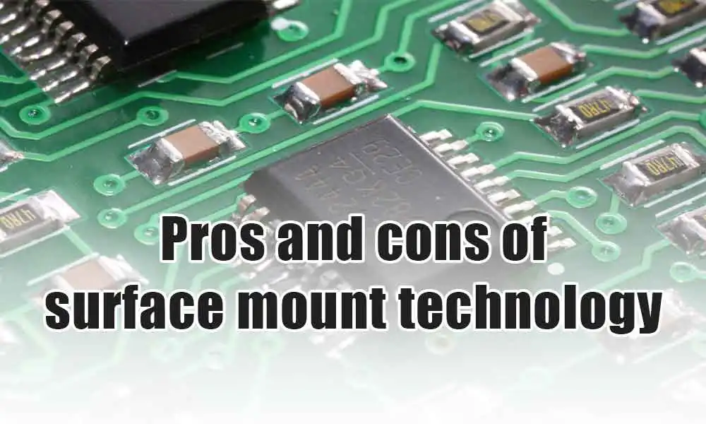
Pros
The component density (the number of components in a given area) is much larger, and there are many more connections between each element. Reduced manufacturing startup time and costs. Consequently, less drilling is required.
When components are placed incorrectly on a soldering iron, the surface tension of the molten solder will pull them into proper alignment with the solder pads.
Reduced connection resistance and inductance improve high-frequency performance and make interference less likely to occur.
Cons
It’s more challenging to assemble a prototype or perform component-level repairs manually.
Heat cycling may weaken the solder joints in surface-mount devices. Significant, consequential, or high-voltage components, such as those used in power circuits, are not suited for surface mount technology. Components subjected to regular mechanical stress should use something other than SMT as their only connection technique.
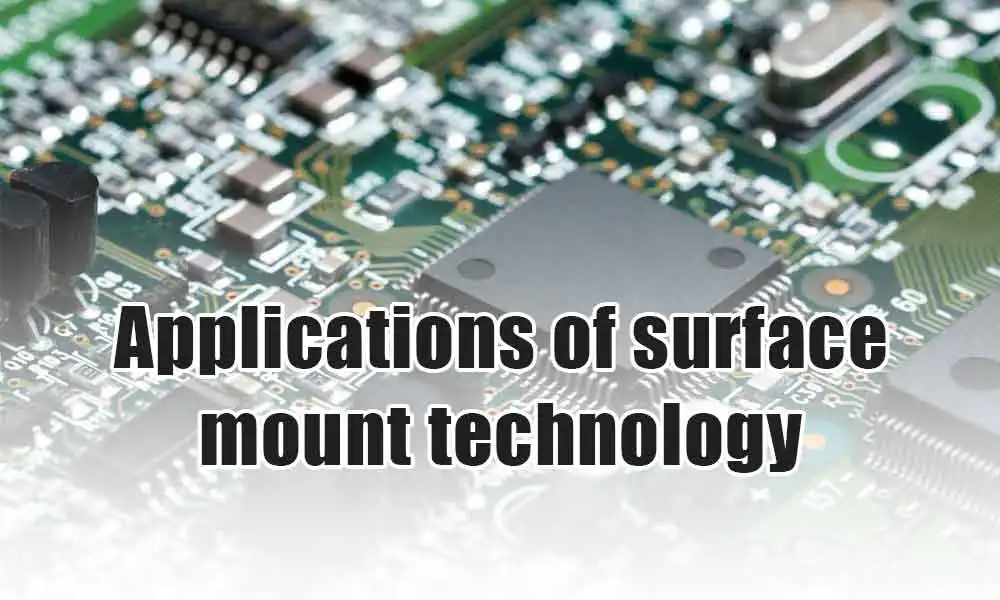
SMT is now widely employed in every PCB production and assembly step. This is because it allows more electronics to be packed into a given volume. As a result, the parts are more compact, and several perform better than their predecessors. They also pair well with automated machinery, so no human hands are needed during assembly.
When working with wired components, automated placement was never a sure bet. All cables had to be custom-made to meet the exact distance between holes, and even then, sometimes, they wouldn’t stay there. In a standard PCB construction, all components are automatically positioned. Rarely will manual intervention be required. The necessity to modify a design so that components fit precisely is significantly reduced when using high-quality circuit boards.
| SMT | THT |
| To put it simply, Surface Mount Technology (SMT) refers to installing electronic parts directly onto a PCB. Since the 1980s, when it first became popular, SMT has been used extensively in producing almost every electronic device.Surface mount technology has become integral to PCB design due to its potential to improve performance and reliability while reducing processing and handling costs.Solder-less surface-mount technology (SMT) eliminates the need to drill holes in a printed circuit board by allowing components to be attached in place. In addition to being smaller, SMT parts are designed to sit flush against both edges of the board. As a result, PCBs have become dense, more efficient, and more compact due to an increased ability to hold more components on each board. | The leads of components are inserted into pre-drilled holes on a bare PCB for through-hole attachment. The through-hole technique was the norm for circuit assembly until SMT became popular in the 1980s.There is widespread speculation that THT may be phased out in favor of Surface Mount, which offers significant cost savings and improved efficiency.But despite its declining popularity, the Through Hole method is helpful in the era of SMT, offering several advantages and niche applications. The most apparent benefit of through hole technology is its durability; presently, annular rings provide a lasting connection. |

In surface mount technology (SMT), electrical components are mounted directly onto the PCB’s surface during assembly and manufacturing (PCB). Due to this method, more of the assembly work needed to make a functional board may be done automatically throughout the manufacturing process.
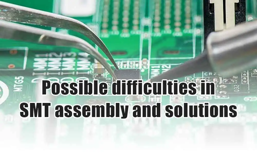
Problems
● Transmission reliability
● Revamping of Printed Circuit Boards
● Validation
● Supervising
Solutions
● Substitute for Oxidized Paste
● Beads of Solder
● Fast-Transit
● Open Insufficiency
1. The standard of the used materials
The material utilized is the primary consideration in SMT production, and the material’s operation directly impacts the reflow soldering quality.
2. Pad arrangement for PCBs
The PCB design must be precise for the SMT method to function well.
3. Mold construction and layout
Applying solder paste to the printed circuit board (PCB) is a design masterpiece. However, the precision of the mold’s structure directly affects the quality of the printed solder paste.
4. Prepress conditions
Standard printing processes rely on blade speed, pressure, cleaning procedures, and frequencies.
5. Utilization of devices and equipment
High-density printing with fewer modules per board requires careful, repeated labor, affecting the solder paste‘s stability.
6. Links between components
The devil is in the details because using components correctly requires careful component selection, proper connection, and the application of pressure.
7. Conducting solder reflow
If reflow soldering can reliably provide decent results, Surface mount technology will improve. To accomplish this goal, the connections on the board must be of the highest quality.
So that’s about everything you need to know about integrated circuits and how they work. We at Qtech are always ready to give you solid advice about PCBs, PCBA, and ICs. Talk to us today and find out more on what we offer. With over a decade of experience in this field, you’re guaranteed quality always.